Detecting Lightning with a Raspberry Pi
I’ve always been fascinated by both lightning and remote sensing. Giving the rather obvious and ubiquitous nature of the former, it provides the perfect opportunity to do a bit of the latter. Lightning detection and the resulting data — while obviously useful for protecting people, pets, and equipment — can also help with things like storm identification, tracking, and intensity quantification.
Various methods can be used to detect lightning. Commonly it involves sensing the electromagnetic radiation generated by a strike. Most people have probably heard this at some point as static, crackles, and popping sounds on an AM radio. Some detectors are capable of picking up the flashes of light produced within a cloud, even during the day when they usually can’t be seen by the human eye due to sunlight. Occasionally lightning will emit a brief pulse of gamma radiation — something a new instrument aboard the International Space Station is set to study.
In this post I’ll explore using a RaspberryPi to interface the AS3935 Franklin Lightning Sensor IC from ams (Austria Mikro Systeme). The AS3935 is a programmable sensor that can detect lightning activity up to 40km away. It uses a proprietary hardwired algorithm to filter out noise and man-made “disturbers” and estimate the distance to the leading edge of the storm; has programmable detection levels, threshold settings, and antenna tuning; and unlike many previous terrestrial lightning sensors can detect both cloud-to-ground and intra-cloud lightning activity.
If you’d rather skip all the boring details and jump straight to the results, scoll down or click here.
The Details
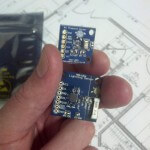
Rather than rounding up the specific components in small quantities, laying out a PCB, and trying to hand-solder the rather small (4x4mm) MLPQ-16 package, I used the MOD-1016 breakout board from Embedded Adventures. The AS3935 requires a supply voltage range of 2.4 – 5.5V, which will work perfectly with the RaspberryPi’s 3.3v GPIO logic levels. It can be interfaced through SPI or I2C. By default the MOD-1016 comes configured to use I2C but can easily be switched to use SPI through a couple of solder jumpers on the board. In my setup I’ll be sticking with the default I2C configuration.
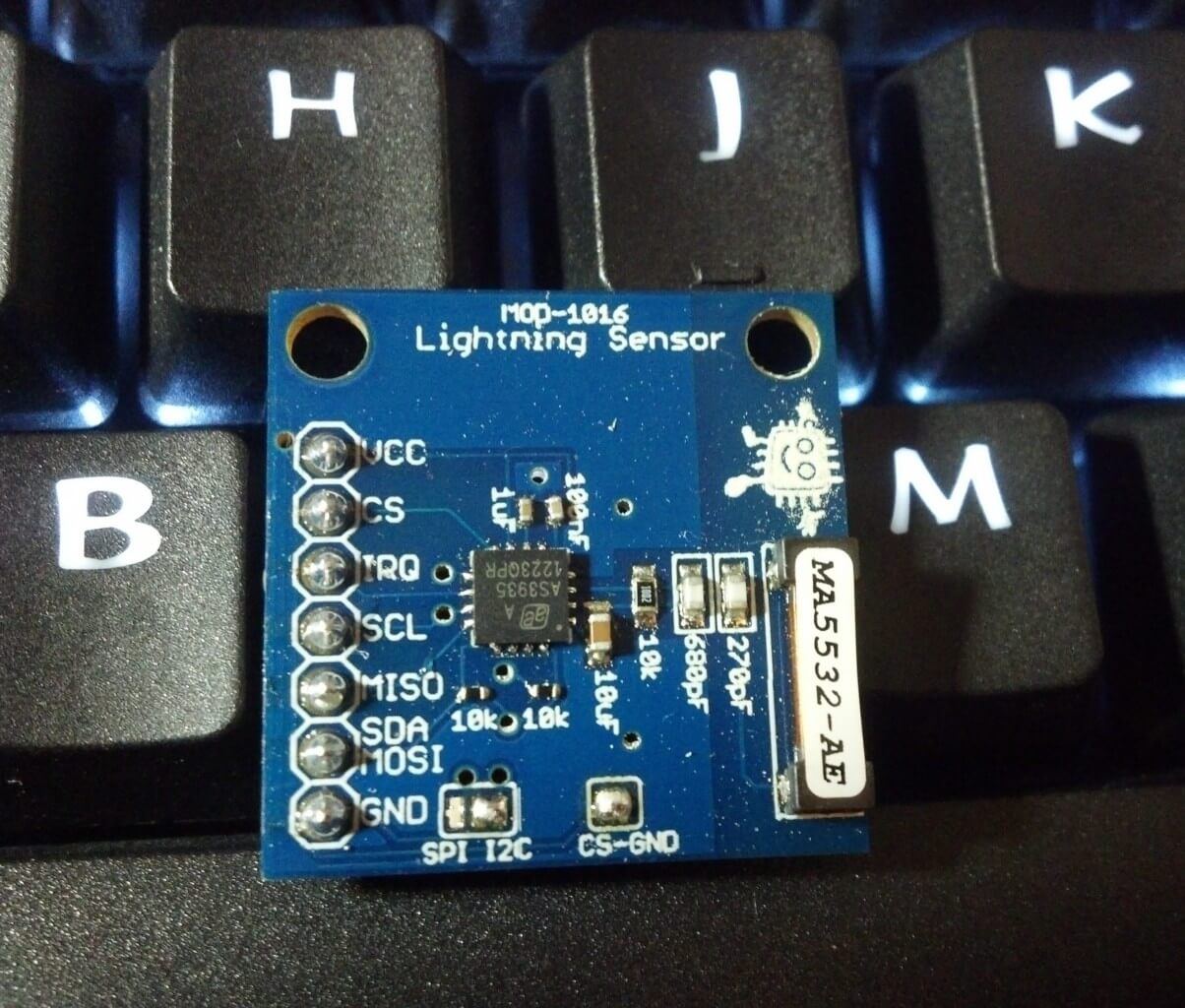
AS3935 breakout board from Embedded Adventures
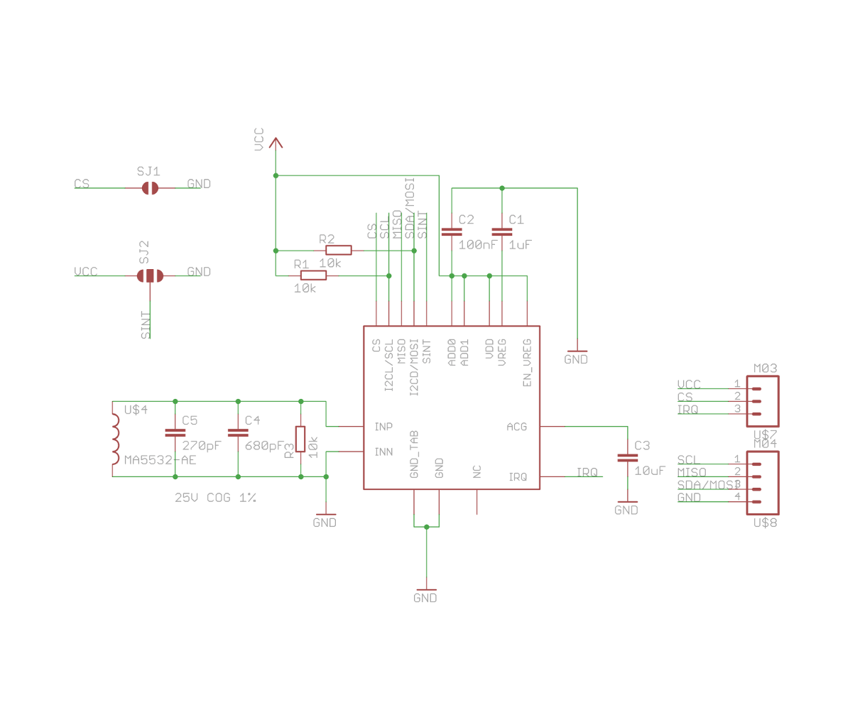
MOD-1016 Schematic
This project served as a nice introduction to the I2C protocol for me. I had used the 1-Wire protocol before to interface some DS18B20 temperature sensors, but I2C is much more widely used and so I was glad to have the opportunity to dive into it. In this post I’ll be covering the details necessary to communicate with the AS3935 from the RaspberryPi over I2C, but if you’d like more information, Byte Paradigm provides a wonderful introduction to I2C and SPI.
If you don’t already have your RaspberryPi configured to use the I2C protocol you’ll have to install a couple packages and load a couple kernel modules. Adafruit has a wonderful guide here, but basically you just need to install the python-smbus and i2c-tools packages, and load the i2c-bcm2708 and i2c-dev kernel modules. Doing this on the Raspbian distro might go something like this:
### Installs the packages
~ $ sudo apt-get install python-smbus
~ $ sudo apt-get install i2c-tools

### Loads the kernel modules
~ $ sudo modprobe i2c-bcm2708
~ $ sudo modprobe i2c-dev

### Make sure modules load on boot
~ $ echo "i2c-bcm2708
i2c-dev" | sudo tee -a /etc/modules
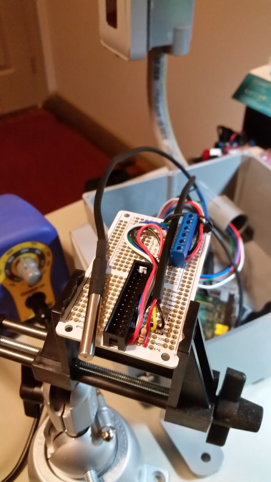
Wiring up the MOD-1016 to the RaspberryPi is relatively simple. With I2C you only need two wires (SDA & SCL) — besides power and ground, of course — to communicate with multiple devices. The AS3935 issues interrupts to alert the microcontroller to events, so we’ll need one additional wire for that. I used a standard breadboard and a RaspberryPi Cobbler from Adafruit to mock-up the circuit. The MOD-1016 (AS3935) connects to the RaspberryPi as such:
| MOD-1016 | RaspberryPi |
|---|---|
| GND | Ground |
| VCC | 3.3v (pin 1) |
| IRQ | GPIO 17 (pin 11) |
| SCL | SCL (pin 5) |
| SDA | SDA (pin 3) |
One thing to note about I2C is that it was designed for inter-chip communication, often between integrated-circuits found on the same PCB. In I2C the lines are held high by pull-up resistors and pulled low to indicate the opposite state. The time it takes to bring the line back up to VCC varies depending on the value of the pull-up resistor and the bus capacitance. The I2C specification limits the maximum capacitance to 400pF, which typically restricts the practical distance to within a few meters. There are ways to extend the max length if needed. The most obvious being an I2C bus extender. Slowing down the clock rate can also help increase max distance. Also, be aware that if using twister-pair cable like CAT-5 for I2C connections not to run the SCL and SDA lines together over the same twisted-pair. Use separate pairs and tie the other line in each pair to ground.
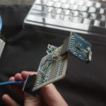
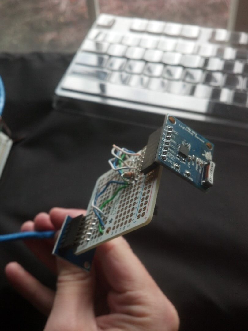
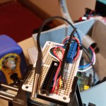
The images below show the MOD-1016 breakout breadboarded along with a MS5611 Barometric Pressure Sensor from Embedded Adventures and a FTDI Friend from Adafruit.
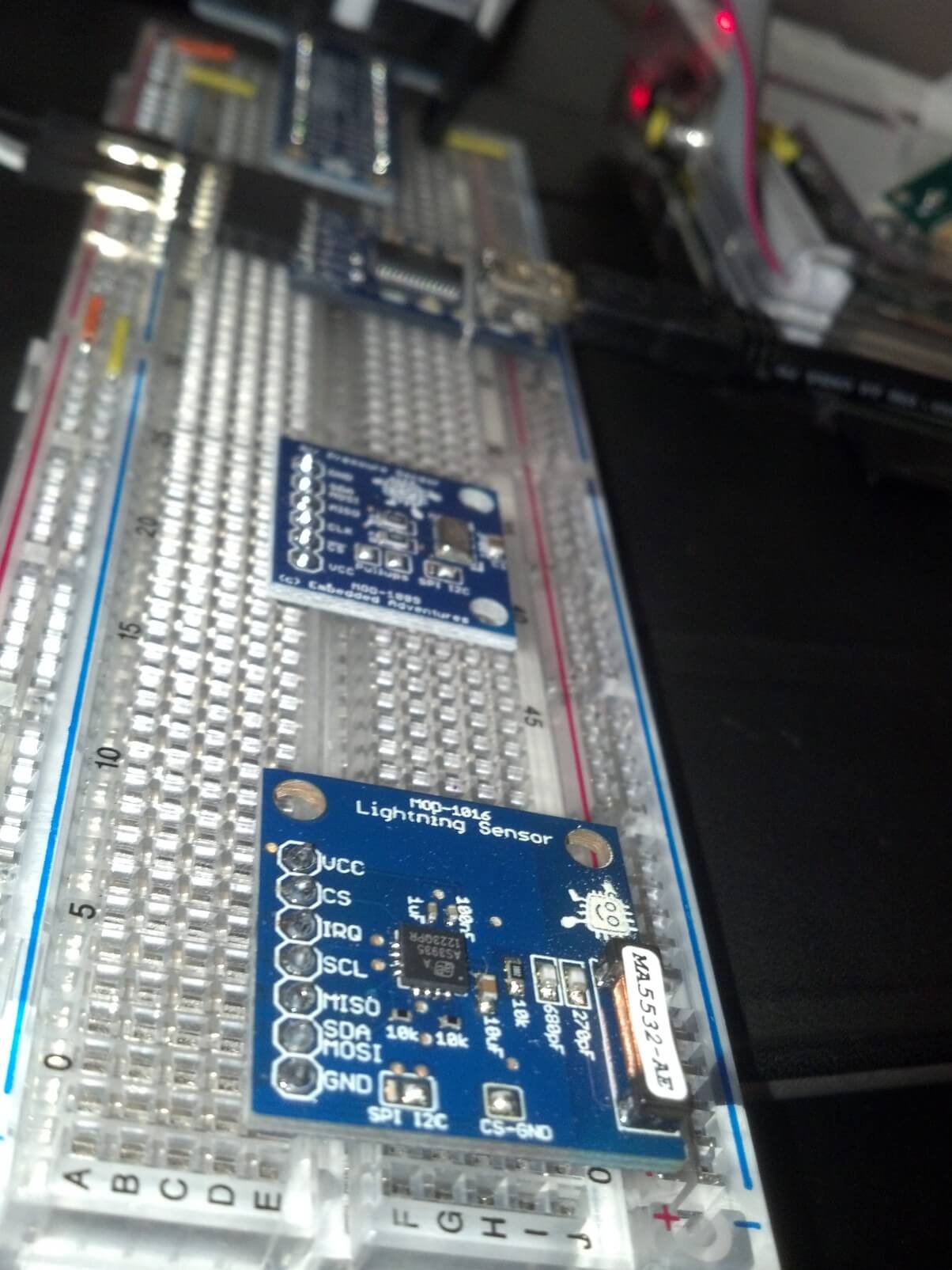
Breadboarded MOD-1016
Wired up and functioning
Once everything is wired up you can use the command i2cdetect to see whether I2C is working and can communicate with the sensor. If using an older RaspberryPi (with 256MB ram) you will run the command as shown below with an I2C bus ID of 0. If using a newer RaspberryPi though use 1 instead. In the output below you can see the AS3935 (0x03) and the MS5611 (0x76) has been properly detected.
~ $ sudo i2cdetect -y 0
     0  1  2  3  4  5  6  7  8  9  a  b  c  d  e  f
00:          03 -- -- -- -- -- -- -- -- -- -- -- --
10: -- -- -- -- -- -- -- -- -- -- -- -- -- -- -- --
20: -- -- -- -- -- -- -- -- -- -- -- -- -- -- -- --
30: -- -- -- -- -- -- -- -- -- -- -- -- -- -- -- --
40: -- -- -- -- -- -- -- -- -- -- -- -- -- -- -- --
50: -- -- -- -- -- -- -- -- -- -- -- -- -- -- -- --
60: -- -- -- -- -- -- -- -- -- -- -- -- -- -- -- --
70: -- -- -- -- -- -- 76 --
Now to actually use the sensor we’re going to need to be able to interact with it. This is done by reading and writing to registers within the chip. Registers are memory locations used to store bits for things like configuration and input/output. In a way they are like digital DIP switches, where bits or series of bits are used to indicate or set various states. For example, with the AS3935 it is possible to clear the statistics built up by the algorithm by toggling the 7th bit (bit 6) of the 3rd register (0x02). Tables and mappings describing the register locations and functionality can be found in a device’s datasheet. For example, the register table from the AS3935 datasheet is shown below.
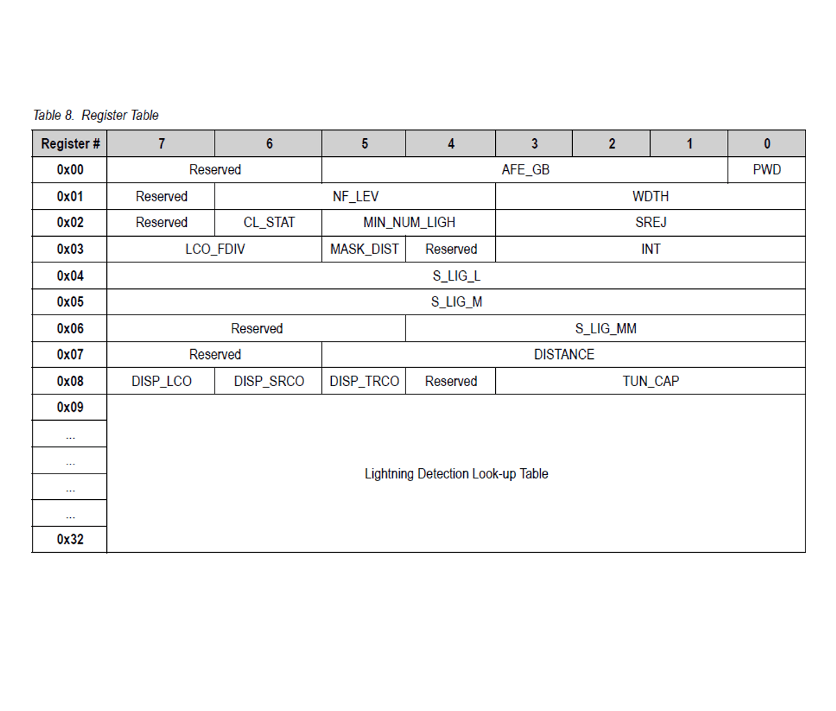
AS3935 Register Table
Most languages and platforms have tools or libraries available for working with I2C. On Linux for instance, the i2c-tools package provides utilities like i2cdetect, i2cget, i2cdump,and i2cset that can be used from the command line. For python, the SMBus module provided by the python-smbus package offers the bindings needed for accessing the I2C bus. Often though there are higher-level libraries available for devices that abstract away the details of working with individual registers. Instead of having to know which bits to read or write to which registers you can often just instantiate a class and call methods to interact with the particular device.
For working with the the AS3935 in python, the RaspberryPi-AS3935 library written by Phil Fenstermacher is available. Installation instructions can be found on the GitHub page. It provides useful methods as well as a nice demo script to get you up and running. To see available methods and their arguments take a look through the RPi_AS3935.py file.
The AS3935 uses a parallel RLC circuit as an antenna and needs to be tuned to a resonant frequency of 500kHz ±3.5%. To compensate for variances there is up to 120pF available internally though tuning capacitors that can be activated in steps of 8pF. Through a register setting the AS3935 can output the resonant frequency on the IRQ pin allowing an external device to measure it and tune the antenna appropriately by activating the necessary tuning capacitors. Luckily the MOD-1016 breakouts from Embedded Adventures comes with the tuning capacitor value displayed on the outside of the anti-static bag. This makes the calibration routine much simpler. When using the above library it is as simple as calling the calibrate() method and passing the tuning capacitor value as an argument. More details on the antenna design can be found in the AS3935 AMS Hardware Design Guide.
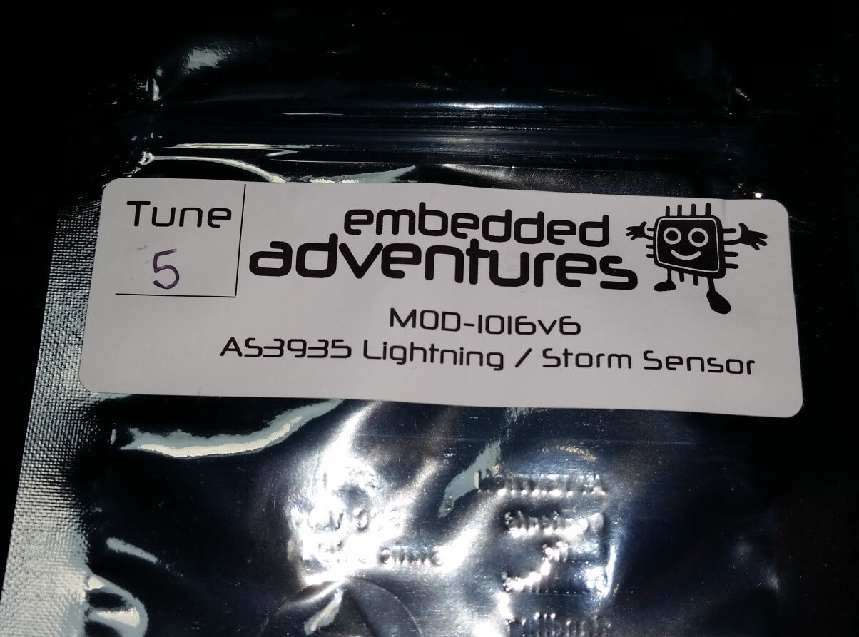
Tuning capacitor value listed on MOD-1016
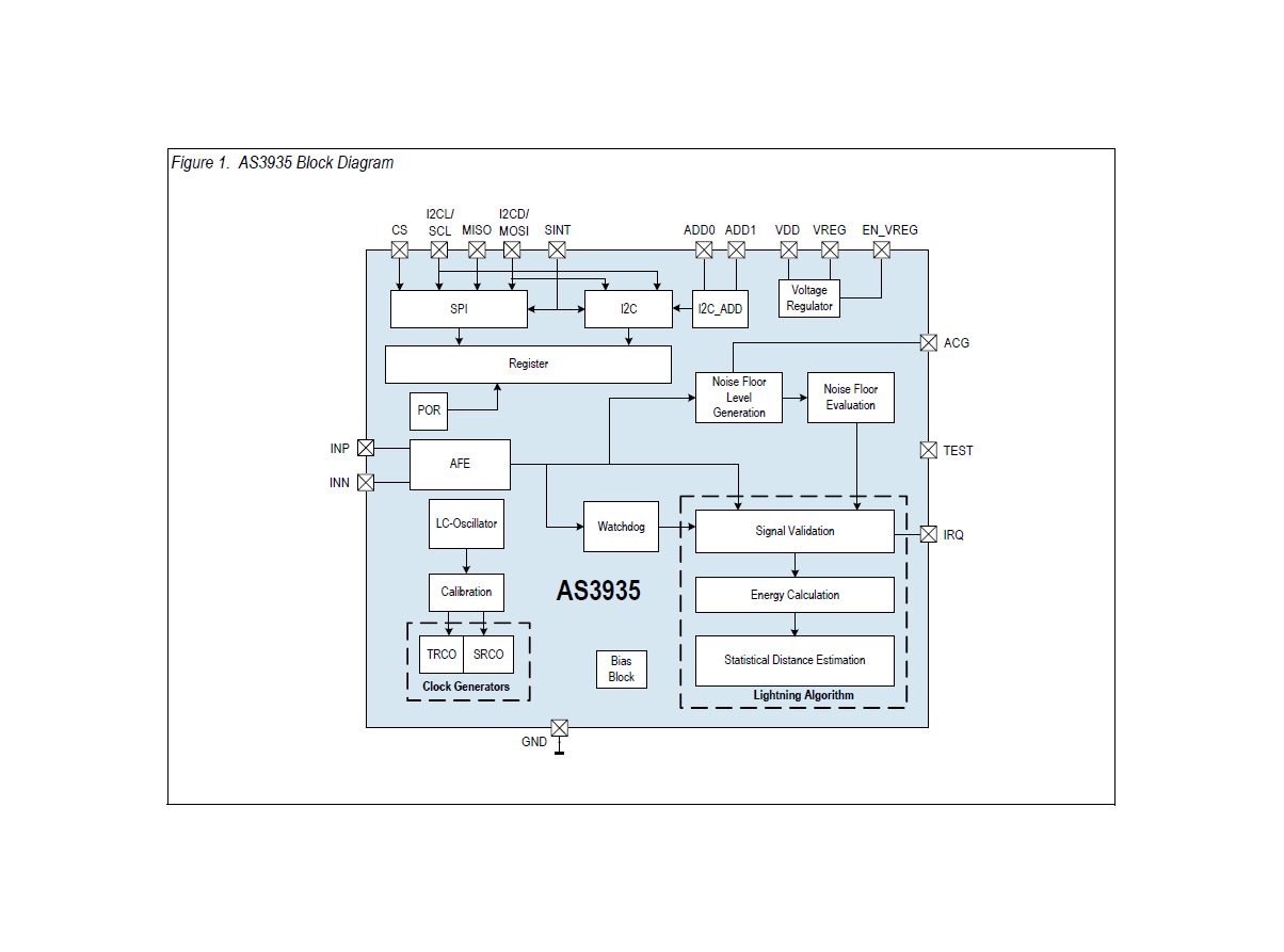
AS3935 Block Diagram from datasheet
The signal from the antenna then feeds into the AS3935 IC to be amplified and demodulated by the the analog front-end (AFE). By default the AFE gain is optimized for an indoor environment. If placing the sensor outdoors you will want to toggle AFE Gain Boost setting to the outdoor value. Another important setting is the noise floor threshold. When the noise floor level crosses the noise floor threshold an interrupt is issued which allows the external device to then raise the threshold. The RaspberryPi-AS3935 library includes methods for easily changing both of these settings.
When an event is detect, the AS3935 notifies the host device by pulling the IRQ pin high momentarily. Handling these interrupts in Python on the RaspberryPi involves registering a callback function that is ran whenever it detects the rising edge of the IRQ pin being pulled high. According to the datasheet you must wait 2 milliseconds after an interrupt is issued before reading register 0x03, bits 3-0 to determine what the event was. The value will indicate one of four types of events.
| REG0x03[3:0] | Event |
|---|---|
| 0000 | Distance estimation has changed |
| 0001 | Noise level too high |
| 0100 | Disturber |
| 1000 | Lightning |
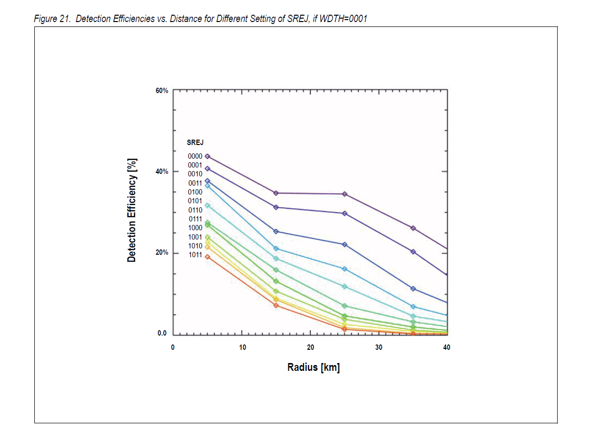
Although the algorithm used by the AS3935 to qualify and quantify events is proprietary and hardwired, there are some settings available to tweak the process. The first of which involves the “watchdog”. This is a circuit that monitors the output of the AFE and sends the signal onto “signal validation” once it crosses a certain threshold. The watchdog threshold can be adjusted through register 0x01, bits 3-0. Signal validation is the first step of the algorithm and is where “disturbers” are sorted from real lightning. Register 0x02, bits 3-0 allows you to adjust the spike rejection threshold. (At the time of this writing the RaspberryPi-AS3935 library is lacking methods for adjusting the watchdog and spike rejection thresholds. However it shouldn’t be too difficult to add them.) Both of these settings can help cut down on false-positives, however improved disturber rejection comes at the expense of detection efficiency. The graphs below from the datasheet demonstrate this.

By default an interrupt will be issued each time a disturber is detected. This can be useful initially to see that the sensor is working, but in practical use these events tend to clutter up things. The AS3935 has the ability to mask disturbers by setting register 0x03, bit 5 to 1. This will prevent interrupts from being issued for any additional disturbers. Another setting that may be useful for eliminating false positives or controlling output volume is the “minimum number of lighting events” threshold. This will cause an interrupt to be issued only if this minimum number of strikes is detected within a 15 minute interval. The default is 1 strike, but you can raise that to 5, 9, or 16 with register 0x02, bits 5-4.
If an event passes signal validation as a legitimate lightning strike, then calculations are made to estimate the energy of the event and stored along with timing data which then allows the AS3935 to make a statistical distance estimation to the head of the storm from 0 to 40km in 14 steps. The distance is represented directly in register 0x07, bits 5-0 as kilometers (binary encoded). 0x3F (111111) means an event was out of range. 0x01 (000001) means the storm is estimated to be directly overhead.
This covers most of the details needed to get up and running with the AS3935. Though I would encourage you to read through the datasheet and hardware design guide.
The Results
For the most part I was able to get decent results using the default settings and the demo script adjusted for the particular tune cap value. I was having an issue though where it would seem to go completely deaf and fail to register even nearby lightning strikes. After a few weeks of replacing and testing everything from the power supply to the wiring, I finally determined the issue was probably software related. Adding a few additional milliseconds wait before and after calling the calibration routine — making sure the internal RC oscillators have time to stabilize — seemed to fix the problem. Some online have suggested re-running the calibration routine after any changes to the settings.
I also have occasional false-positives where a lightning strike or two is detected on a perfectly clear day. Adjusting the watchdog and/or spike rejection thresholds should take care of these. Adding the methods to adjust these thresholds to the RaspberryPi-RS3935 library and rewriting the monitoring script will be my next steps. I would also like to put together an API to collect this and other real-time sensor data and display it online. Currently I just have a text log being uploaded via FTP every 15 minutes.
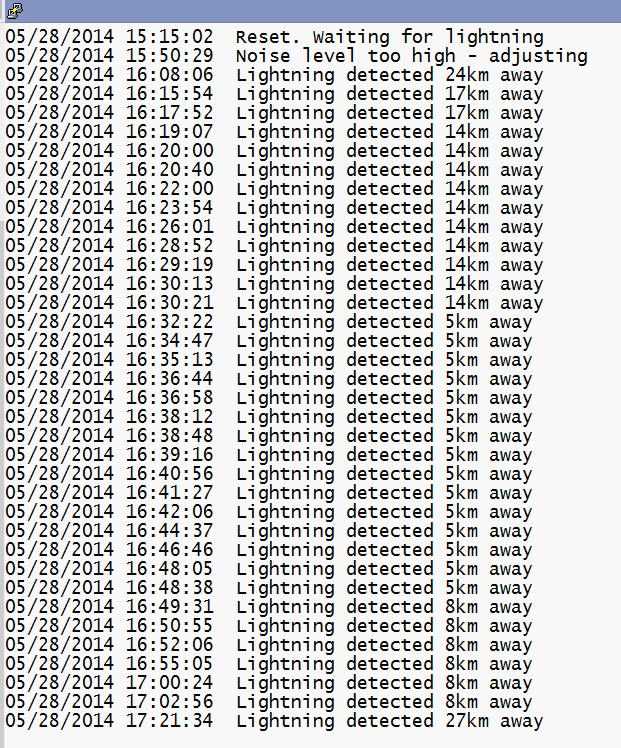
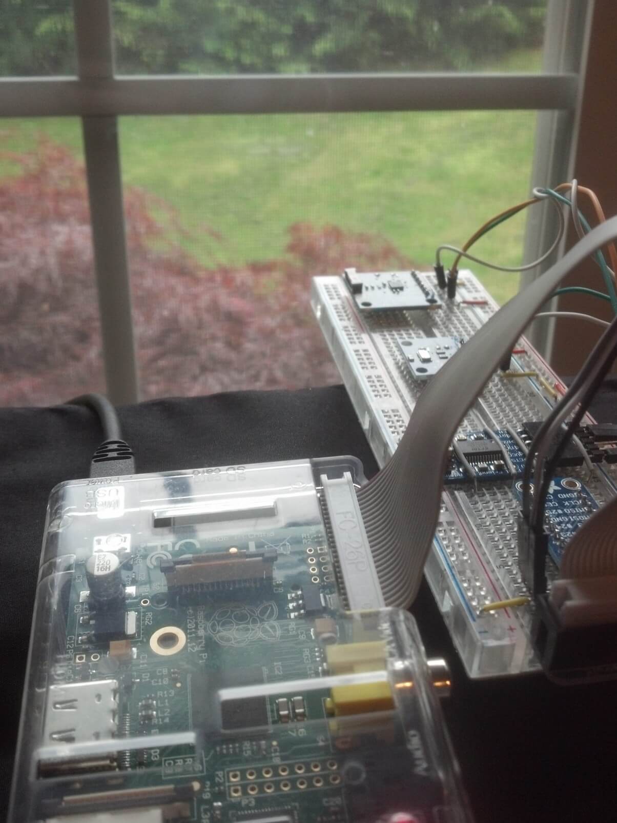
Tracking an afternoon thunderstorm

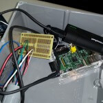
Testing the AS3935 on a stormy day
I decided to use a RaspberryPi for this project rather than something like an Arduino or another microcontroller for a couple of reasons. An obvious one being I had a couple of them lying around. The main reason though was that I wanted this to be a web-connected platform so that I could capture and display events remotely. I also wanted it to be able to sit outside and connect wirelessly. For $45 ($35 RaspberryPi + $10 USB WiFi adapter) it’s hard to beat.
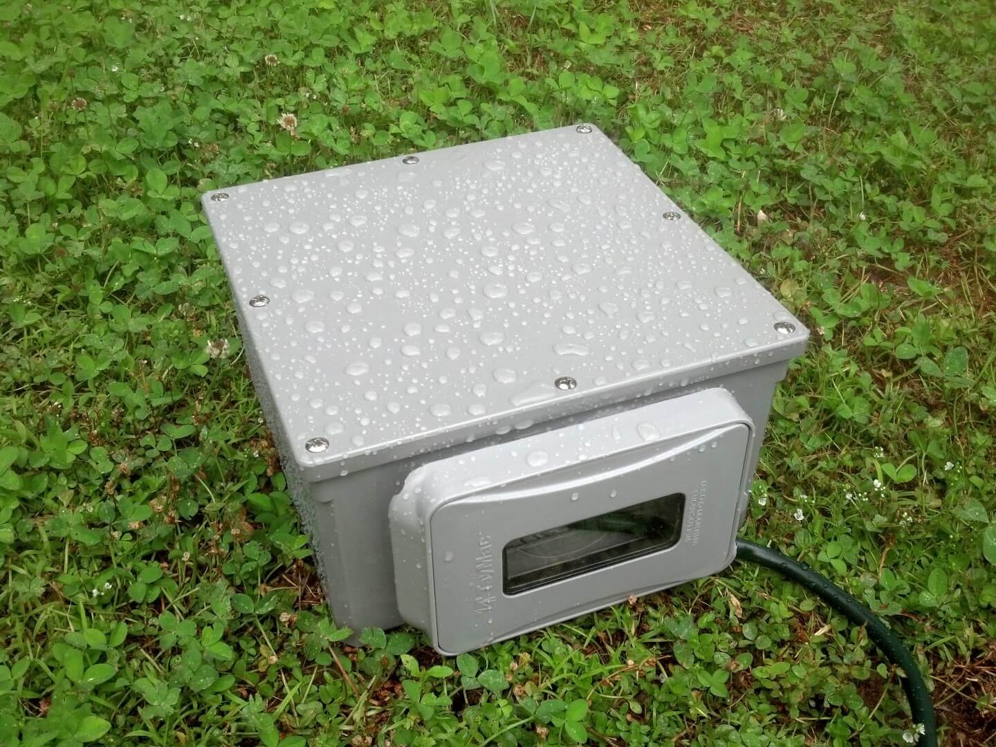
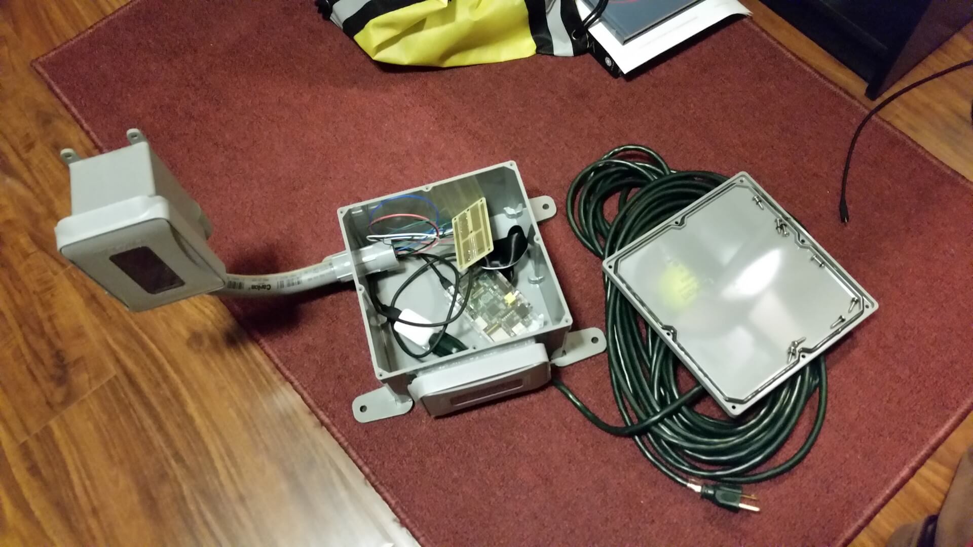
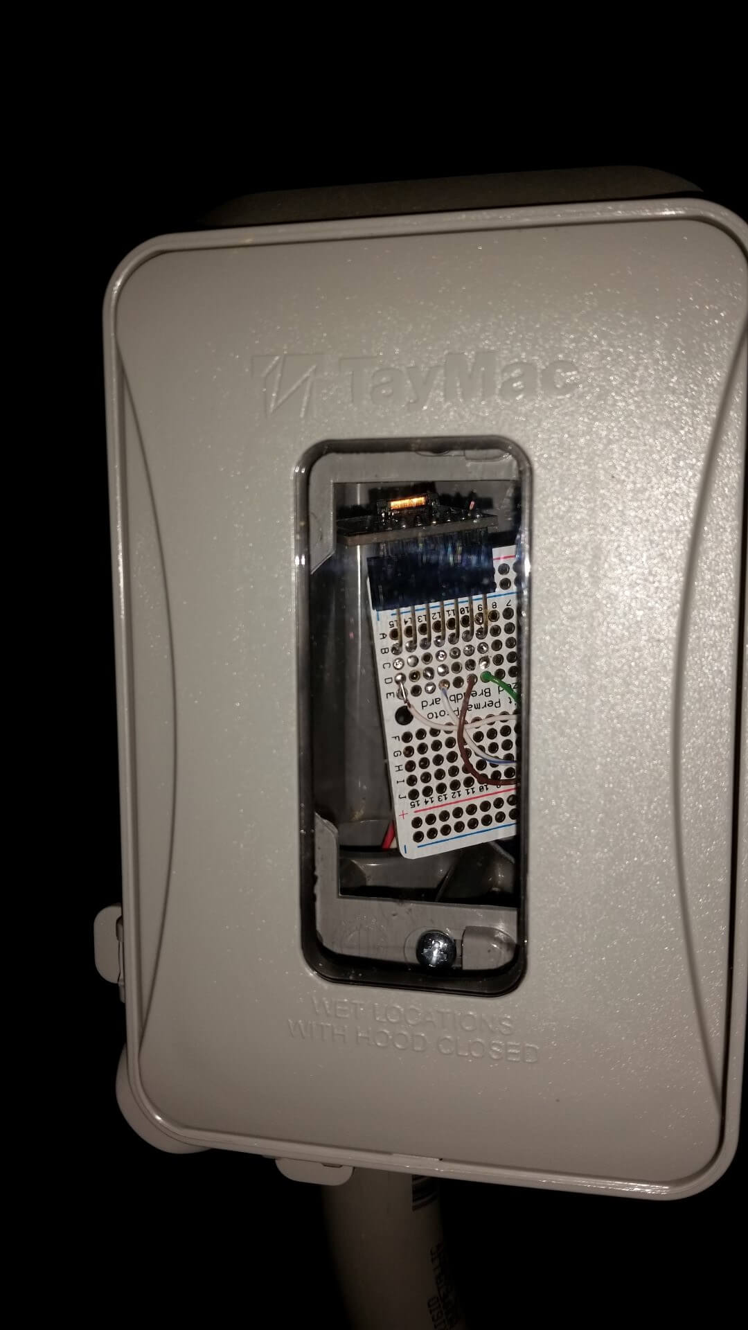
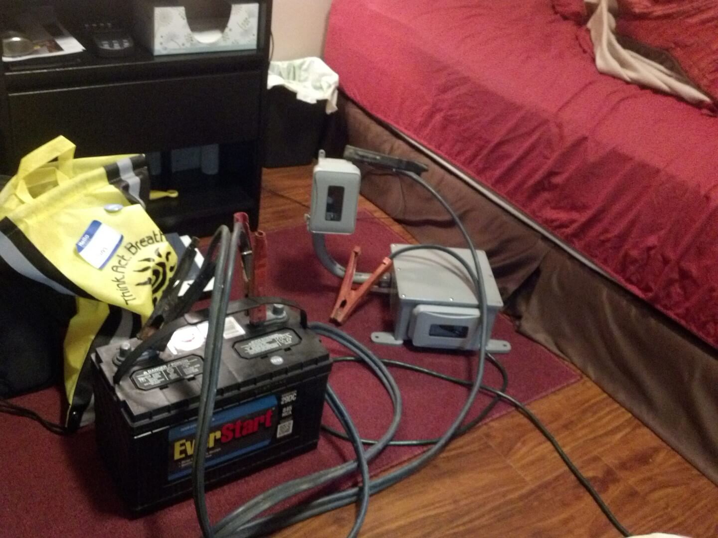
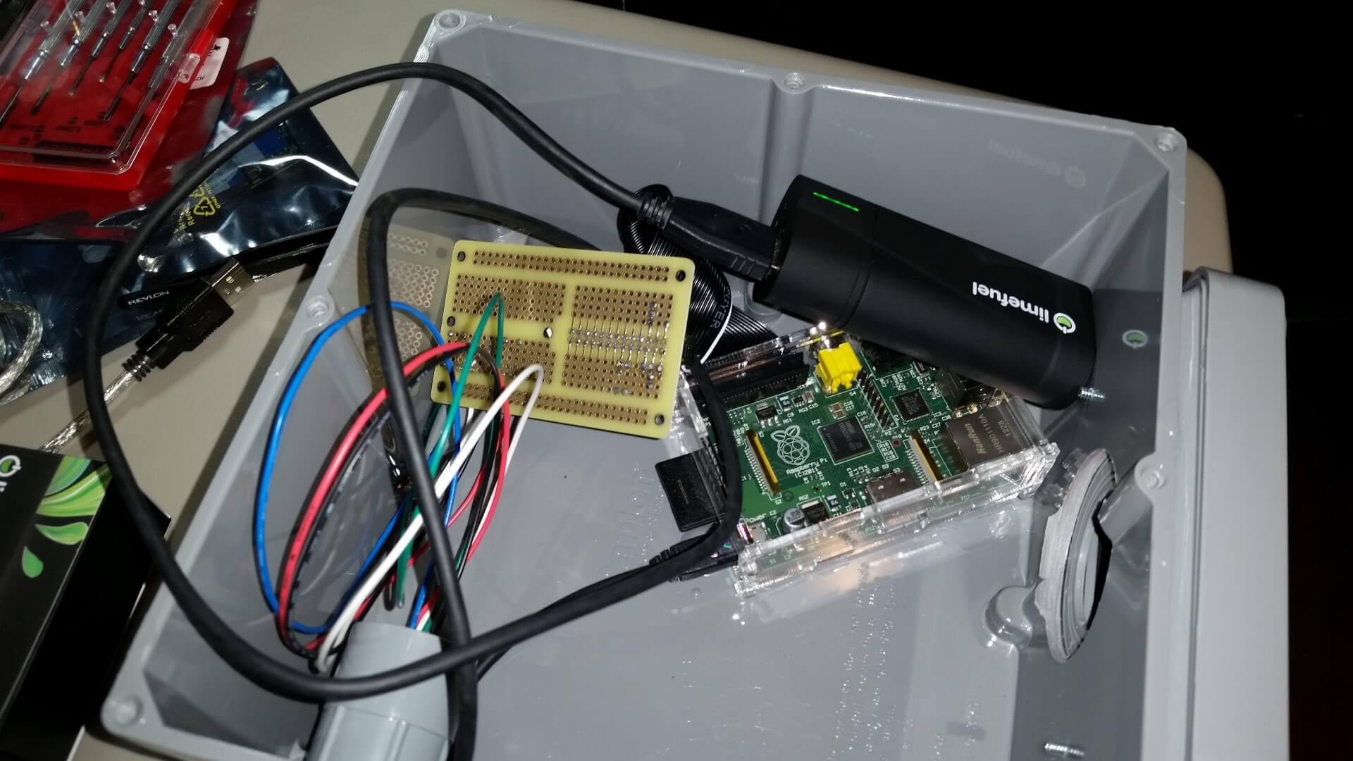
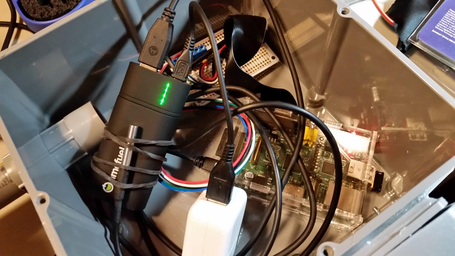
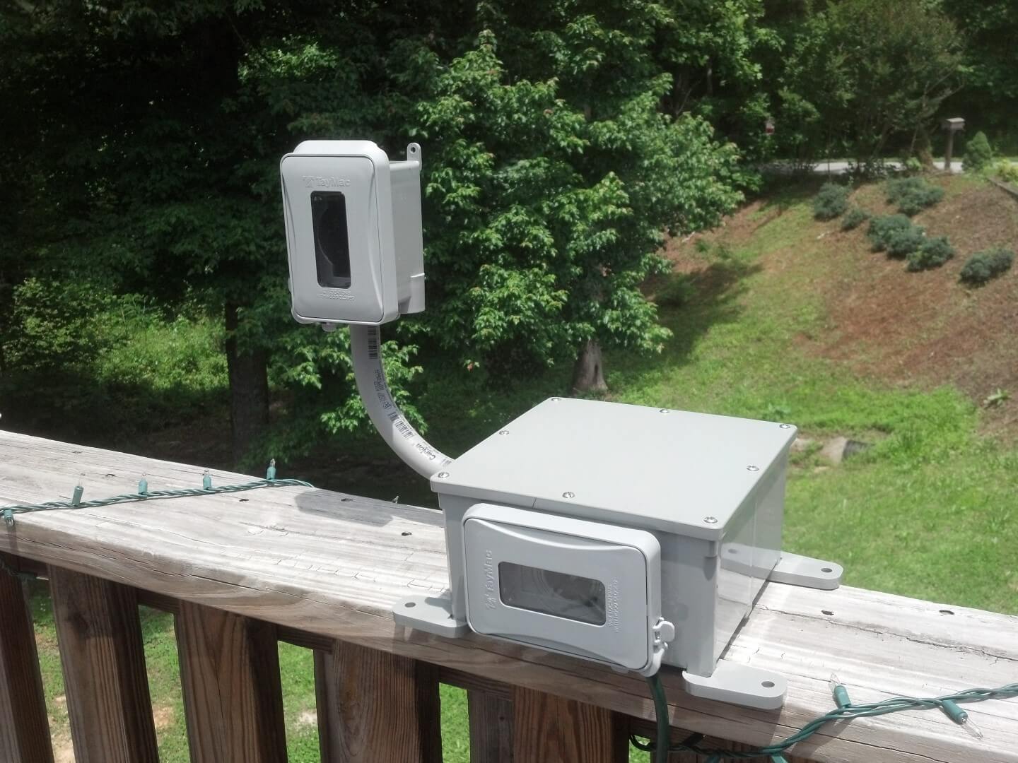
To be able to collect other outdoor sensor readings I put together a simple weather-resistant project box using a PVC enclosure, outlet box, gaskets, and weather-proof outlet covers. I ended up using an iPad charger for the power supply and Limefuel 6000mAh battery pack as UPS for the RaspberryPi. A DS18B20 temperature sensor was used to first get an idea of ambient box temps, and later to monitor the temperature of the battery pack.
-
- AS3935 and MS5611 sensors

-
- Sensor modules wired up
-
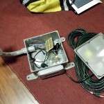
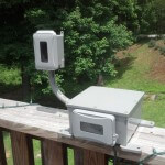
- Second version with external sensor pod
-
- Making some sparks
-
- Rewiring the breakout
-
- Soldering on a DS18B20 temperature sensor
-
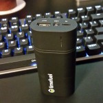
- 6000mAh Limefuel battery pack

-
- Runtime test – 7.5 hrs on 6000mAh
-
- All wired up
-
- Ready to go
I’ll update this post or link to updates as I come across additional information or find new ways to use the AS3935 lightning sensor. Something I would like to explorer down the road is the possibility of using multiple devices spaced >1km apart to triangulate thunderstorms.
Feel free to ask questions in the comments below and I’ll do my best to answer them.
That’s a really cool project, congrats.
I wonder if it would be possible to make the AS3935 into a very compact lightning detector for hikers and mountain climbers. It would just need like 4-5 LEDs to show the rough distance of the lightning strikes.
What do you think would is the most stripped down microcontroller that could be used for this?
Thanks! It’s definitely possible. The IC itself is perfect for integrating into small personal units. If you want to stick with breakouts like the one I used then something like the 3.3V version of the Adafruit Trinket would probably work for a microcontroller.
Hey Adam,
What is the breadboard you’re using? Also incredible post and exactly what i was looking for!! Hoping to build this for myself soon 🙂
Brendan
Thanks! 🙂 The breadboard came with an Arduino starter kit I bought a few years ago, but I’m pretty sure this is the same one.
It is a perfect system!It is good for testing lighting. Very useful for outdoors work.
Hi Adam
First up – a big thank you: this is a tremendous article!
In my haste to wire my MOD1016 up, I trashed the Embedded Adventures anti-static packaging, and with it the Tune Value!
Some quick coding (while there is lightning overhead) adjusting the tune value in increments (from tune value of 0) has had no effect on the correct detection of strikes!
Any suggestion on how to retro-actively determine the tune value?
FYI: I’m using PCFens demo.py as the basis for my code:
https://github.com/pcfens/RaspberryPi-AS3935
forgive my post – trying to get my hands on a scope and will write to DISP_LCO to calibrate until 500khz.
Now, pardon my ignorance here, I’m just starting into this stuff..
I recently got the BMP085 which uses the same sdl and sda pins as the mod-1016. I assume I just cant solder them together, so what type of hardware do I need to connect both of these sensors?
Thanks
Sorry for the delay, Peter. You should be able to connect them to the same SDL/SDA lines. As long as you have pull-ups somewhere on the lines you should be able to just connect devices up to the bus.
[…] we need more sensors! After reading this blog about lightning detectors and Raspberry Pi, I ordered one pretty […]
Hi Adam,
At first congratulations for your article, You´ve been working really hard and even sharing your accomplishments. I work in Spain as
a maintenance employee in a network located in the southern of the country “The automatic system for hydrologic information” (abbreviated SAIH in Spanish) consisting of a network of remote stations across the Mediterranean Andalusian region)like you can see on our website http://www.redhidrosurmedioambiente.es/.
I´ve developed a lightning detector with the AS3935 and PIC16F877 microcontroller on I2c bus.We´ve eventually installed one in the station number 2 (Sierra Luna) located close to Gibraltar Strait las December. The station is a vhf and uhf radio repeater and its surrounded by several stations (military, TV and so on) so you can imagine the noise level and different kinds of disturbers there´re there. The device under those conditions works ok, it detected 2 nearly strikes during the last storm and at the same time another industrial detector made by Global Atmospherics Inc. located over 50 km farther in Estepona (station number 6) detected 2 far strikes, then I think that´s ok, although I must wait for more storms and compare.
I setted the chip with the basic parameters to work, after tuning with its correct number of capacitors (checked with an oscilloscope, the number marked in the package never matched what I´ve seen during the tunning procedure) , the lowest parameters for spike rejection, watchdog threshold and so on setted as default and the disturbers IRQ disabled. These settings are the best way I´ve worked with, I occasionally get a false strike in my laboratory only caused by fluorescent tubes switching on and off nearby. If you try to mask the disturbers and set the chip all time trying to avoid false strikes the chip becomes seriously deaf, in my way I prefer a false strike sometime(I haven´t obtained anyone in the station so far,)and protect the equipment disconnecting them from the mains than to cry them after burned.(Our commercial devices also detect false strikes sometime).
Well, I don´t know how You´ve been able to work with emmbedded adventures chips, I bought two units and they are completely deaf, I can set them, tuning, recalibrating, reading and writting but, deaf like a wall (it´s a spanish expression). Tautic and http://www.playingwithfusion.com‘s breakdown boards work perfect at same conditions.
As I´m getting new results or discovering something relevant I´ll share them. Sorry for my bad english and thanks again for your article.
Kind Regards.
Juan Carlos
Am I taking these days the integration project AS3935 sensor as my weather station Kit, which are also running through Raspberry B +, I wanted to know if there is a script for installing software to make possible the publication of the results of receiving lightning on the pages of my site…. Maybe if you know examples already operating. Thanks and congratulations for the project that I have a lot of inspiration
Thanks for the comment, Francesco. I’ve been a little distracted with other projects since I wrote this. What I was doing at the time was collecting the data in logs and then uploading them to my site through FTP every 15 minutes. If I were to do it over again I’d probably setup a lightweight REST API with Python to collect data. Another suggestion someone made that sounded interesting was possibly using rsyslog to send/receive event information.
Thanks for the tip!
Hi
I’ve installed this on my RPi, it’s running, and we are currently in a kind of storm (lot of thunder ), but sensors is definitively quiet.
Meaning it’s not working, of RPi code does it catch interrupt… So my dDummy question : how to test it ? 😉
Thanks for your article anyway
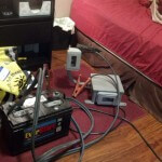
Thanks for stopping by! Unfortunately it can be quite a pain to thoroughly test. I even tried using jumper cables and car battery to generate arcs but the results were hit and miss. You should be able to test interrupts by turning of the disturber masking, but beyond that it just takes a lot of trial-and-error and making sure it’s tuned right.
Adam>>I am VERY new to python, GitHub, etc. Could you possibly give me some help in installing the RPi_AS3935 module from GitHub?
Thanks, Steve
Hi Steve,
My system is currently tucked away in the closet at the moment as I’ve been busy on other projects so I can’t check my setup, but the Readme on the GitHub page is pretty much all you need. You can either install it through pip if you have python-pip installed, or just download the repo as a zip file, extract it, and run:
python setup.py installThe included file – demo.py (view here) has examples on how to use the module.
Thanks, Adam. I downloaded and installed the repository. I am using a program called Weewx for my station. I have two Pi’s, and installed the sensor on my non-station one to experiment with. I and several other users who are just starting to play with the lighting sensor have gotten the same error message:
RuntimeError: Conflicting edge detection already enabled for this GPIO channel
I have found other references to this error, but none of them are related to the lightning sensor, and though I tried some of the suggestions, none have worked.
Would you have any ideas on how to track this down?
Steve
Hi Steve,
I had to reply to your original comment since I only have this setup for comments nesting three deep. It’s been a while since I’ve messed with it so I’m not familiar with something that might have changed since then, but I don’t think that error is unique to the lightning sensor. It sounds like it might be related to interrupt detection. Is it showing that error when you run demo.py? If so, does commenting out
GPIO.add_event_detect(pin, GPIO.RISING, callback=handle_interrupt)make it go away? If so then something else could be registering interrupt detection and causing the conflict. If you can’t work around it or find and stop the conflict you might want to take a look at the GPIO library documentation. If there’s an add_event_detect function there is probably a remove_event_detect function as well that you could try to use to free it up.Hi,
Very good article. Thanks for that.
What would you suggest to test the detector if it is working or not?
There was a storm within about 20-30 km range and no detection happened at all.
I have just noticed the printed number of the tune parameter (3 in my case).
I use WeatherPI “board” to add different sensors.
They have library to support these sensors.
My device seems to be available on the i2c bus as the software was able to read registers.
A tried to add some “disturbance” like mobile phone next to the device (in call), flash (of a digital camera), but nothing strange happened (with the exception the Raspberry stopped working and had to power cycled (Hidden feature of RPis 🙂 )
So no idea how to test if the circuit itself is able to receive signal when it will happen. The “live” test yesterday evening was not successful, however I left “0x0f” the calibration instead of “0x03” (found on the package).
Zoli
Hi Zoli,
You’ll definitely want to make sure you get that calibration value added in there. I wouldn’t expect it to work properly when not tuned, especially at that range. The 40km range listed is just the theoretical max detection distance. The furthest out I was able to detect a strike was 34km. If you look at some of the charts in the datasheet you’ll see that over that distance detection efficiency drops to almost nothing. So I definitely wouldn’t rely on a storm 20-30km out for an accurate test.
As far as simulating disturbers go, after getting it properly tuned you’ll probably see it pick them up just from electrical noise in the environment. Though people have used those clicky piezo igniters (like a grill lighter) to test them. I used a car battery and jumper cables to generate sparks, but wouldn’t recommend that as I did end up burning holes in a bedspread from it.
[…] I’m a bit late getting this post out as a followup to last year’s Detecting Lightning with a Raspberry Pi, the topic of project enclosures never really gets old. Especially cost effective and readily […]
Hi I am working on communicating with the AS3935 lightning sensor but I have the Franklin board. I am using SPI communication and I am trying connecting to the device but when I turn it on it says “The Start Frequency Is too High”. What frequency do you set your I2C communication at? I have set it at 750KHz,1MHz, and even 1kHz but it does not seem to start up properly.
I also have a secondary question. I am sending the data byte 0x47 in order to get the distance of the lightning storm. Do I need to have a buffer of 2 bytes in order to get the data or do I need to perform other instructions before I start gathering the data?
I have the Rasberry Pi 2 model B and I am using the wiringPi library in order to setup the GPIO pins.
Any information will be helpful. Thank you
Thank you for your article it saved me a pile of cash. I was going to order the breakout kit from dig-key at around $400. Ordered from Embedded adventures needless to say. I hope to be able to integrate this with my other lighting counter into my wither station software (weewx). Sure to be educational and hopefully fin.
Jerry
yes I was not good at spelling bee competition
Hi, i have an Rasberry PI 3B doest the MOD-1016 work with that?
I want to use the lightning board only. What the easiest way to get things connected. What do i need to buy next to the MOD-1016 board?
Do i need to solder 3 wires to the Rasberry PI 3B?
Can i hook up the MOD-1016 to the GPIO pins. I am gonna use I2C bus. Does it need any resistors?
I want to use an UTP (straight) Cable for it (cat 5).
I am noob in electronics schema’s but i know how to solder. In the above tutorial i get overflowed with information and dont know how to hook this board up to my Raspberry Pi 3b.
I hope i can get some information about this.
[…] hobby gets put on the back burner indefinitely. It has been a couple years since I posted about my last serious project. This month marks a year since we packed up everything, sold the house, and moved to Pittsburgh. […]
Adam, thanks for your article. Following your steps, I was able to get my sensor working almost instantly. Just a small addition: if one uses a Playingwithfusion breakout board, connect the CS pin (sensor) to GND (RPi).
I have a question: what is the approximate max cable length connecting the sensor and RPi? I’m using i2c. Thanks!
Hey Peter,
I’m glad you were able to get your sensor working! Thanks for the feedback! It’s always appreciated. It’s been awhile since I’ve messed with this but if I recall it’s not long at all. Maybe a few meters at most. I remember when I was troubleshooting this setup I had to rule out that I was having cabling issues at even just a meter because it is possible depending on your setup.
Hello Adam, I’m doing a weather station and based on what you did but I’m in trouble when compiling the code, the problem is in the library from RPi_AS3935 import RPi_AS3935, showing the following error: ImportError: No module named ‘RPi_AS3935’. I would appreciate your help as it is very important to continue advancing with my project, I await your answer thanks.
Thanks for another wonderful article. 44005166