Making: Wristband Scanners for Abstractions II
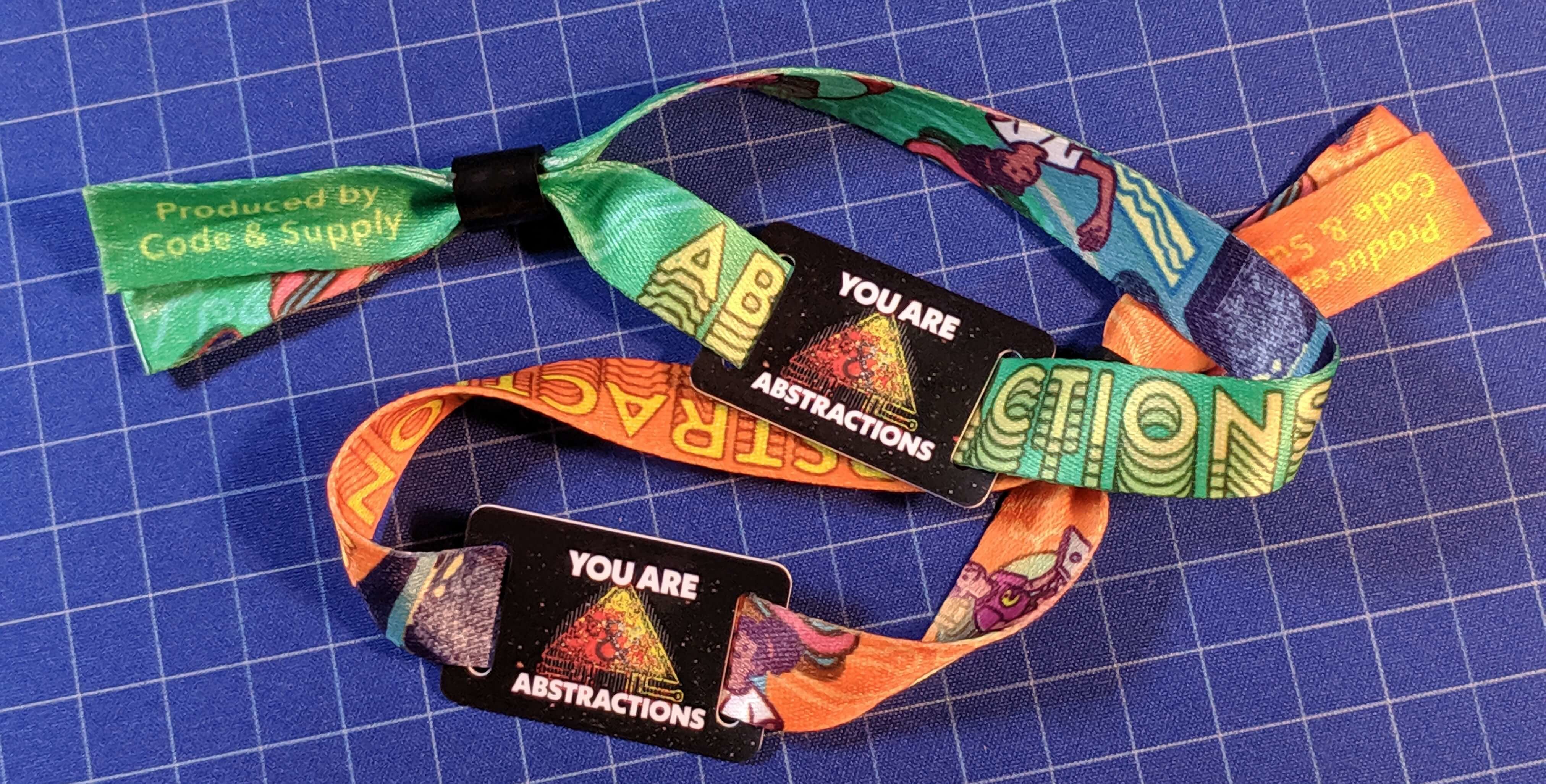
Earlier this summer a friend who runs a local coworking space and organizes events focused on software development reached out asking about the possibility of using NFC/RFID for the upcoming Abstractions II conference here in Pittsburgh. The goal was to use branded festival style RFID wristbands for check-in, area access, side-quests, and sponsor booth sign-ups. The challenge was to try and build the infrastructure ourselves. In this post I hope to provide an overview of the process of building the scanners. I probably won’t be able to cover every iteration along the way but have provided the code and worked to clean it up and comment it so that hopefully it can be useful as a jumping-off point for someone else.
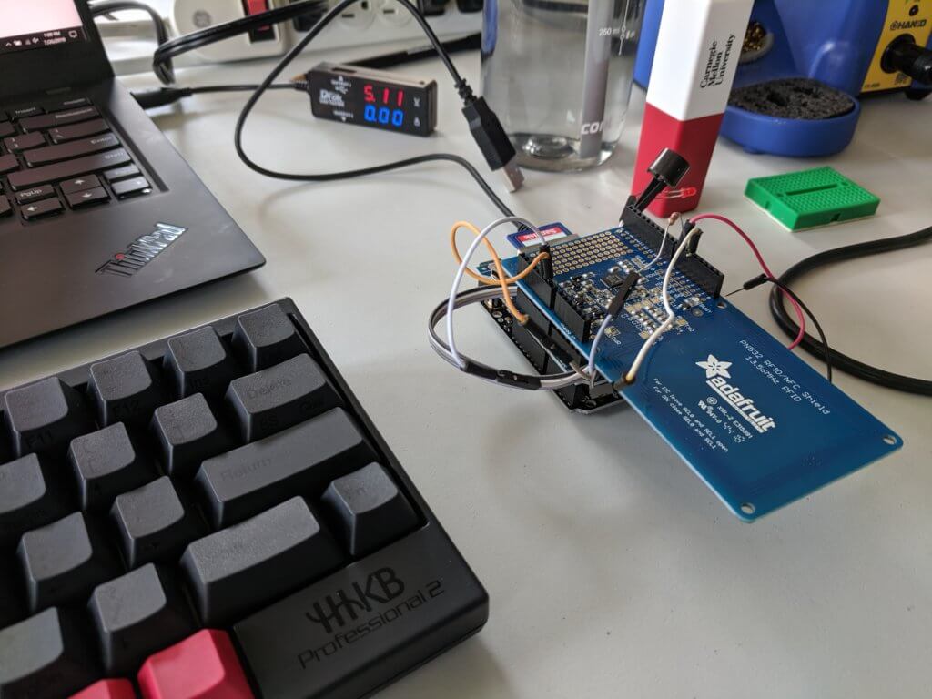
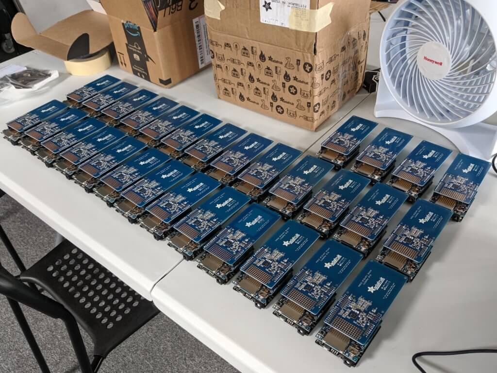
With only about three months until the conference for which he was expecting a couple thousand attendees and would require around forty scanners – and neither of us having much experience in this particular domain – we knew we had to keep it simple. The bare minimum functionality would be to read the UID of a wristband and check it against a list. Given the need for simplicity and the reputation of wifi at conferences I suggested we use SD cards for data storage. Since these would be offline we would also need an RTC (real-time clock) in order to get accurate timestamps.
To make sure we could hit the deadline I figured it would be best to stick with breakouts or shields so that we could keep things modular in case plans changed and also limit the amount of labor needed for each unit. It would also allow us to more easily repurpose components later if we wanted to. After looking online at options and availability I settled on the traditional Arduino shield form-factor. While there is an NFC/RFID breakout that would work with the more compact Feather line of microcontrollers, the antenna is the same size as on the shield version and so while you could reduce the overall bulk you would be adding labor in terms of wiring up the breakouts. I figured the additional prototyping space on the shield might also come in handy for later mounting buzzers and LEDs.

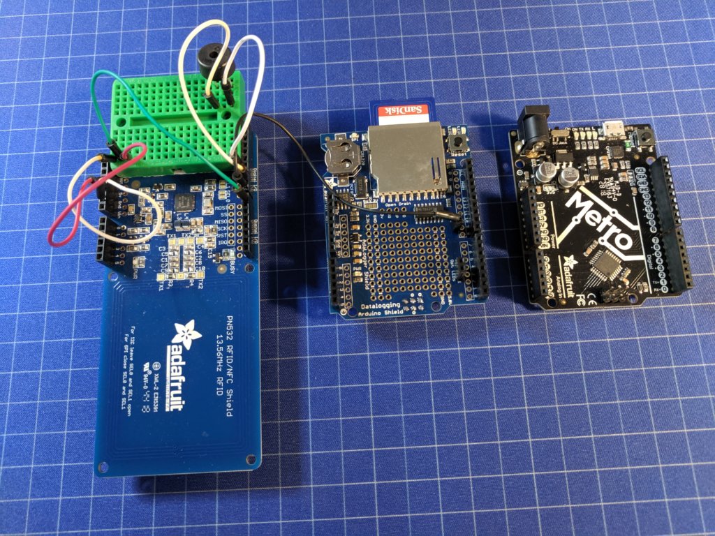
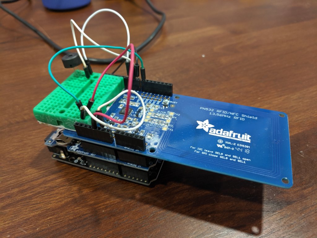
After getting the headers soldered up and the shields assembled it was time to start working on the code. It had been a while since I had put together a project from scratch so I wanted to start simple by just loading up the sample sketches for each component and validating that they worked individually before pulling it all together into a single sketch. (If you installed the libraries through the Library Manager in the Arduino IDE then the relevant example sketches should be available under File -> Examples.) Some of the settings in the examples will need to be adjusted to work with the shield defaults as is. For example, chip select on digital pin 10 for the SD card, I2C settings and the IRQ and reset pins on the PN532 shield. Adafruit does a great job of providing this information through their learning portal. and you can find links to the relevant portal entries in the respective product descriptions on their site.
One logistical issue we had to figure out was how to vary the functionality without having to try and manage multiple versions of identical looking devices or needing to re-flash them in the field. For this I turned to the SD card and put together a function to read settings from a configuration file. The readConfig() function is a bit sloppy as is since each configuration option uses a global character array to hold the value as read from the config file before being converted to the desired type for use. Since we only needed a handful of options though the current version worked good enough for the time being.
The two main modes of functionality we needed to handle was data logging and access control. The data logging mode would be for sponsor/vendor tables so that attendees could scan their wristbands if they wanted to sign up for a contact list. As you can probably guess, the access control mode would be for controlling access to areas such as checking attendees in at the entrances or limiting access to the pro and speaker areas.
For both practical and privacy reasons we opted to only use the UID of the wristbands for either mode. The only additional information that was written to the in tag memory was a URL containing the UID that could be used for registration purposes which I’ll detail in a later post. By utilizing only a unique identifier and not having the scanners networked any data collected would have to be processed after the fact in order to connect it to personally identifiable information. Attendees could also choose just what information they wanted to share through their registration profiles when the data is later processed.
For the access control mode I created a function that would search a configurable text file for the UID being scanned. Since at the time we weren’t exactly sure how we were going to handle the process of exporting allowed UIDs to the cards I added the option to include a comma separated access level (0-9) onto the end of the UID. This way we could either vary the lists or create a global list and vary the access levels. I was initially worried about the time it would take the arduino to search through a couple thousand lines of a text file character by character, but after a few iterations of the search function I was able to get it to where the 2000th entry could be found in just under a second, which for a worst case scenario didn’t seem too bad.
One thing to note regarding the UIDs of RFID/NFC tags is that they are – in the case of these Mifare Classic tags – just 4 literal bytes, and there really isn’t a standardized way – or at least one that I could find – to convert them into a numeric value. Typically you’d just push the bytes together and convert that into a number, but the order in which those bytes are read can vary. I found this out when the numbers printed on some of my test tags didn’t match the value I was getting myself. This just means that when building a system like this you have to make some initial decisions regarding how the UIDs will be processed and then document them and watch out for assumptions made later down the road.
Now that we had the functionality and performance needed it was time to add some lights and sounds and figure out what we were going to do about cases. For sound I had been testing it along the way with a little passive piezo buzzer I had laying around in a typical configuration with one leg connected to a digital output and the other to ground through a 100Ω resistor. While this worked it wasn’t that loud, lacked software volume control, and sounded choppy when trying to play a tune. To get around this I decided to drive the piezo differentially with both legs hooked up to digital outputs simulating an A/C signal using the toneAC library. While you would typically use a resistor due to the piezo functioning like a capacitor and possibly allowing too much current through when used at higher frequencies, it seems like it can vary quite a bit depending on the particular component and use case. After some testing with this setup the most I could get through the piezo we were using was about 5ma, which was well within limits, and whatever risk it might have posed would probably be worth having one less component to deal with.
The one issue I ran into with this setup though is that it requires you to use the hardware PWM functionality of the microcontroller (pins 9 and 10 on the Atmega328) however pin 10 was being used by the data logging shield for chip select functionality. To get around this I moved chip select to pin 8 which required cutting a small trace on the bottom of the data logging shield and jumpering the CS pad to another pin. While this was an extra step, having a louder better sounding buzzer with software volume control was definitely worth it in the end.
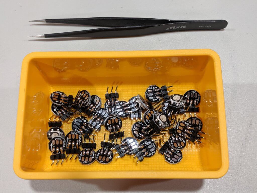
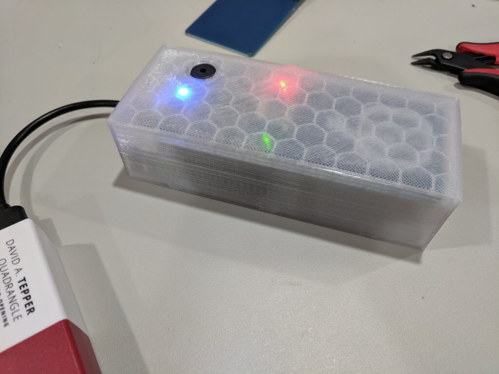
While working on the prototype I had been using the small surface mount LEDs that come on the data-logging shield for testing. However for the final version we definitely wanted something bigger, brighter, and possibly with more colors. Since it had been quite a few years since I had messed around within anything more than that standard red and green LEDs I was dreading wiring up and controlling RGB LEDs on forty devices. Especially since memory was already pretty tight with the SD card operations. Luckily though it turns out you can now get affordable individually addressable LEDs that only need connections to 5v, ground, and a digital pin of your choosing. Soldering on some right-angle header pins made for an easier connection to the proto area on the shield. Combined with the FastLED library these little LEDs were a pleasure to work with and I will definitely be using more of them in the future.


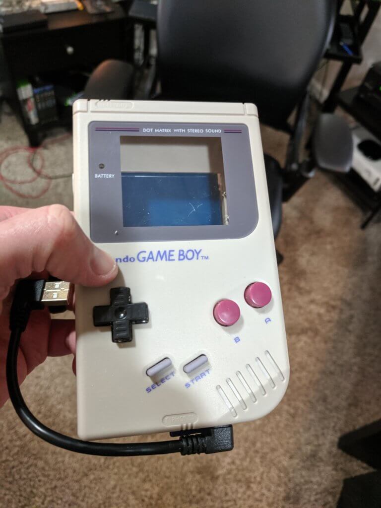
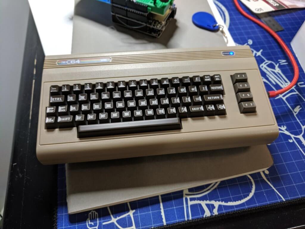
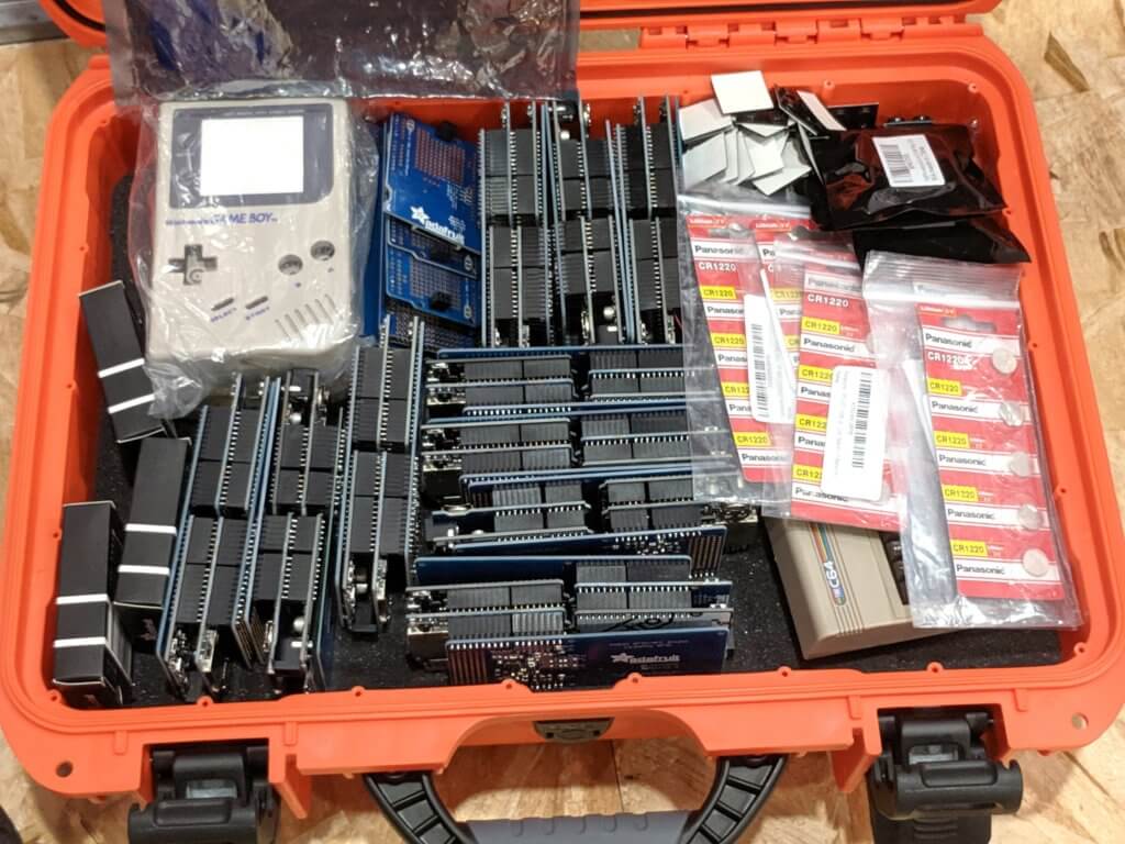
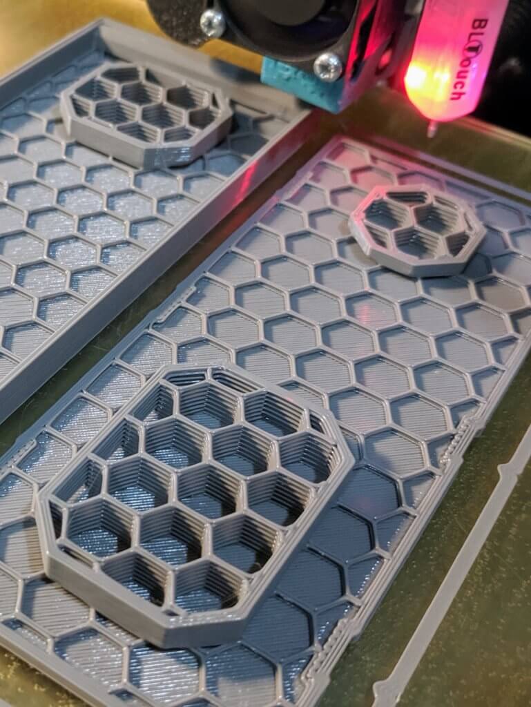
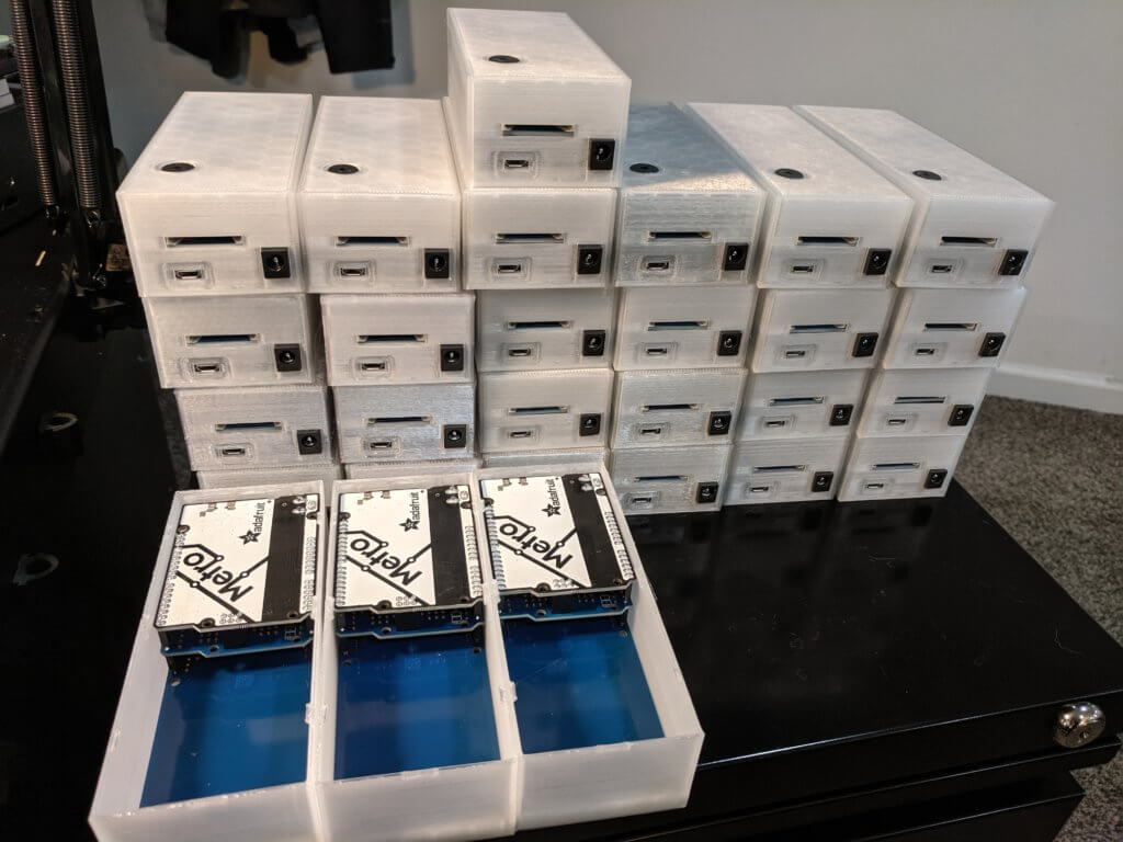
Now that those final pieces were in place it was time to start working on a case design. By now we were down to just over a week left and unfortunately a 3D printer can only print so fast. We also had a few more esoteric cases we wanted to try and use such as old Game Boys and a couple replica mini Commodore 64 devices. Since those would be a last ditch effort I wanted to make sure we had enough regular cases just in case. After an evening with Fusion 360 I was able to come up with a workable minimal case design that I hoped would print fast enough.
The biggest challenge in designing a case like this was accounting for the variances in the position of soldered components, most notably the DC barrel jack and the piezo buzzer. After making a couple adjustments over the course of a few test cases and coming up with a better way to position the buzzers during soldering things started moving smoothly. Before I would use a piece of tape to hold the LED and buzzer on the board while soldering them and then add a dab of hot glue afterwards to reinforce the LED since it was just soldered onto the pins via pads. Instead I started combining them by adding a drop of hot glue first for both the LED and buzzer, then inserting and positioning the components, and then later going back and soldering everything. This allowed me to position them exactly where needed while also securing them for soldering in batches.

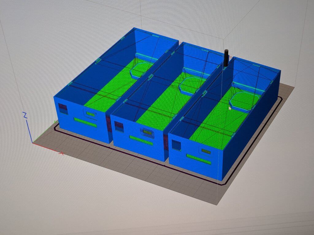
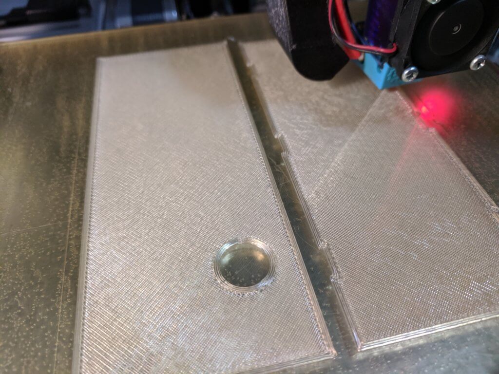
Typically I prefer to use PETG filament for something like this as it’s durable and has a nice texture. The downside is that you have to print slower and hotter than with something like PLA. The first handful of cases I printed with a partial roll of Taulman TECH-G I had on hand and they came out great so I ordered another roll to arrive the next day. Unfortunately though it showed up with the vacuum bag punctured which must have caused it to absorb moisture because I suddenly started getting clogs and jams which is pretty unusual with my printer. At this rate I would be lucky to get just enough done if I kept it going 24/7 without any more breakdowns, so I decided to try a little half-spool of clear PLA I had laying around and while I still preferred the texture of PETG the clear PLA would do just fine. Another benefit of gong with PLA was that I could get it here locally just down the street, which turned out to be a good thing since I ended up going through two rolls of it. After some speed optimizations to the slicing profiles (S3D processes) I was able to get them to print roughly 3x faster than the PETG versions which allowed me to get them all done plus some spares. The one downside to printing so quickly was that the corners on the bottoms weren’t as precise and required a bit of filing into order to fit properly, but a couple minutes of filing was totally worth knocking hours off the print times.
The last step was to see if we could do anything with the miscellaneous “retro” cases. We had messed around previously with trying to fit a unit into a Game Boy case and it looked like it was doable but was definitely going to be a tight fit. The only modifications I had to make for these to work was to move the buzzer position to the middle of the stack and attach the LED with a length of wire so that it could be positioned behind the screen. Leftover clear PLA filament was used to print a light diffuser to go behind the screen for the LED. All of this was held in place with hot glue.
There was no way the scanners were going to fit into the C64 replicas as is due to the height so I decided to separate the RFID shield with some jumper wires and secure it with some foam and a generous amount of hot glue. It probably would have been easier to just solder the wires between the shields, but it was late and I had the jumper wires handy. The LED was mounted with hot glue in place of the original power indicator light. The only modifications that needed to be done to the case was trimming off some of the mounting posts for the original PCB and a bit of filling to make room for the SD card slot. All of the original internals were saved for later reuse.